Chapter 9 | I/O
Privilege, Priority
Privilege and priority are two orthogonal notions, meaning they have nothing to do with each other.
Privilege
It's all about the right to do something.
Supervisor privilege indicates privileged.
A promgram is executing in supervisor mode to indicate privileged, or user mode to indicate unprivileged.
Priority
It's all about the urgency of a program to execute.
Every program is assigned a priority, specifying its urgency as compared to all other programs.
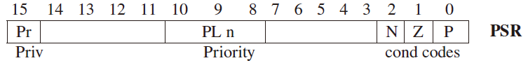
The Processor Status Register, PSR
\(\text{bit[15]}\) specifies the privilege. There are two privilege modes.
1indicates supervisor privilege.0indicates unprivileged, or user mode.
\(\text{bit[10:8]}\) specifies the priority level (PL) of the program.
- the highest priority level is 7 (PL7), the lowest is PL0.
- e.g.
000for user,100for keyboard input,110for power supply,
111 for machine check, which means something goes wrong.
\(\text{bit[2:0]}\) contains the currnt values of the condition codes.
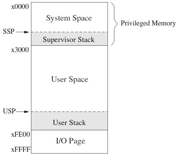
Memory Address Space of LC-3
System Space \(\text{x0000 to x2FFF}\)
It contains the various data structures and code of the operating system.
- Privileged
- System Space
- Supervisor Stack
- Supervisor Stack Pointer, SSP
User Space \(\text{x3000 to xFDFF}\)
All user programs and data use this region of memory.
- Unprivileged
- User Space
- User Stack
- User Stack Pointer, USP
I/O Page \(\text{xFE00 to xFFFF}\)
It identifies registers that take part in input and output functions and some special registers associated with the processor.
e.g. PSR is assigned address \(\text{xFFFC}\), MCR (Master Control Register) is assigned address \(\text{xFFFE}\).
- Privileged
Stack pointer
Each space has a stack pointer. Since a program can only execute in Supervisor mode or User mode at any one time, only one of the two stacks is active at any one time.
Register 6 is generally used as the stack pointer for the active stack.
Two Registers, \(\text{Saved\_SSP}\) and \(\text{Saved\_USP}\) are provided to save the SP not in use.
Input / Output
Basic Characteristics
All I/O activity is controlled by instructions in the computer's ISA.
Memory-Mapped I/O
It uses the same data movement instructions that are used for loading or storing data between memory and GPR.
The I/O device registers are mapped to a set of addresses which are allocated to I/O device registers rather than to memory locations.
The LC-3 uses memory-mapped I/O.
Another scheme : Special I/O instructions
It uses special input and output instructions to control I/O devices.
Asynchronous and Synchronous
I/O devices usually operate at speeds different from that of a microprocessor, and not in lockstep.
Asynchronous not in lockstep with microprocessor
To control processing in an asynchronous world requires some protocol or handshaking mechanism.
The Simplest Form of Synchronization: flag
A single flag, which is a one-bit status register, is called the ready bit.
Each time the typist types a character, the ready bit is set to 1. Each time the computer reads a character, it clears the ready bit to 0.
Interaction
The processor and the typist each is doing its own thing. they need to interact.
The issue of interrupt-driven and polling is the issue of who controls the interaction.
Input from the Keyboard
Input Registers
KBDR, keyboard data register
A data register that contains the character to be input.
Address \(\text{xFE02}\)
\(\text{bits[7:0]}\) are used for the data, \(\text{bits[15:8]}\) contains \(\text{x00}\).
KBSR, keyboard status register
A synchronization mechanism to let the processor know that input has occured.
Address \(\text{xFE00}\)
\(\text{bit[15]}\) contains the synchronization mechanism, which is the ready bit.
Basic Input Service Rountine
When a key on the keyboard is struck, the ASCII code for that key is loaded into \(\text{KBDR[7:0]}\), and the electronic circuits associated with the keyboard automatically set \(\text{KBDR[15]}\).
When the LC-3 reads KBDR, the eletronic circuits associated with the keyboard automatically clear \(\text{KBDR[15]}\).
INPUT_LOOP  LDI     R1, KBSR
            BRzp    INPUT_LOOP
            LDI     R0, KBDR
            BRnzp   NEXT_TASK
KBSR                .FILL   xFE00
KBDR                .FILL   xFE02
Implementation
Output to the Monitor
Output Registers
DDR, display data register
A data register that contains the character to be output.
Address \(\text{xFE06}\)
\(\text{bits[7:0]}\) are used for the data, \(\text{bits[15:8]}\) contains \(\text{x00}\).
DSR, display status register
A synchronization mechanism to let the processor know that output has occured.
Address \(\text{xFE04}\)
\(\text{bit[15]}\) contains the synchronization mechanism, which is the ready bit.
Basic Output Service Rountine
When the LC-3 transfer an ASCII code to \(\text{DDR[7:0]}\) for outputting, the electronics curcuits of the monitor automatically clear \(\text{DSR[15]}\) as the character processing begins.
When the monitor finishes processing the character on the screen, the electronic curcuits of the monitor automatically set \(\text{DSR[15]}\).
OUTPUT_LOOP LDI     R1, DSR
            BRzp    OUTPUT_LOOP
            STI     R0, DDR
            BRnzp   NEXT_TASK
DSR                 .FILL   xFE04
DDR                 .FILL   xFE06
Implementation
Prompt
the message printed on the monitor to let the person sitting at the keyboard know that the program is waiting for input from the keyboard.
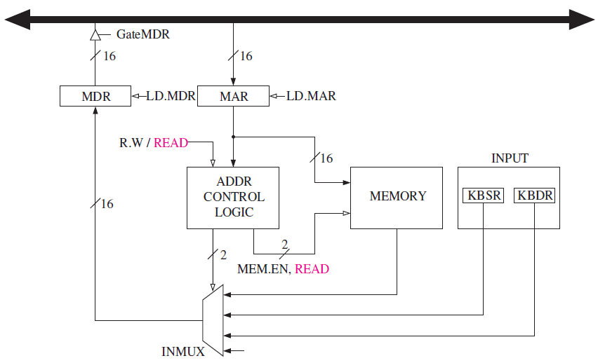
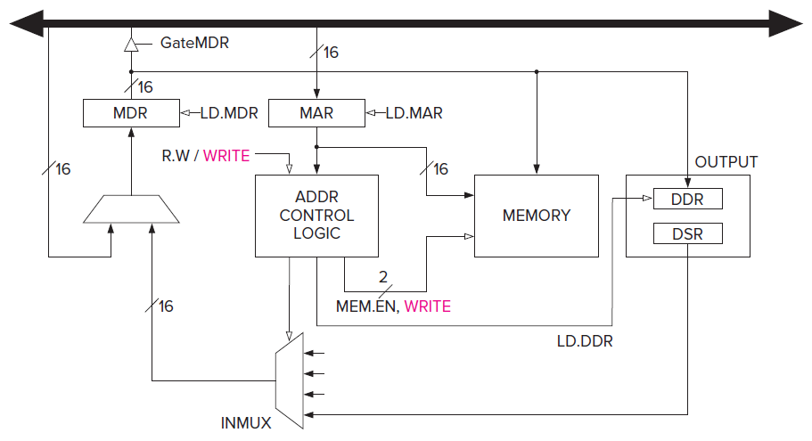
Implementation of Memory-Mapped I/O, Revisited
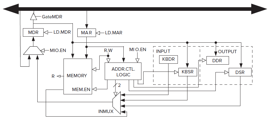
MIO.EN indicates whether a data movement from/to memory or I/O is to take place this clock cycle.
MAR contains the address of the memory location or the memory-mapped address of an I/O device register.
R.W indicates whether a load or a store is to take place.
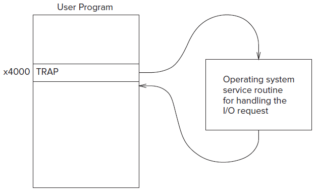
Operating System Service Rountine
It's not an easy way to control I/O activity with many programs, so in general it's ill-advised to give user programmers access to these registers and the addresses of hardare registers are part of the privileged memory address space.
The simpler and safer solution to the problem of user program requiring I/O, involves the TRAP instruction and the operating system.
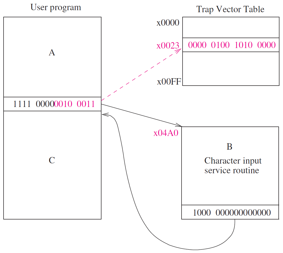
TRAP Mechanism
The trap mechanism involves several elements.
- A set of service routines executed on behalf of user programs by the operating system
- A table of the staring address of these 256 service routines.
- The table is stored in memory locations \(\text{x0000 to x00FF}\).
- The table is called the System Control Block or the Trap Vector Table.
- The TRAP instruction.
- A linkage back to the user program.
TRAP and RTI Instruction
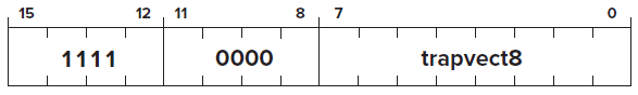
TRAP
Opcode \(\text{[15:12]} = 1111\)
Operand
- \(\text{[11:8]}\) : must be
0000 - \(\text{[7:0]}\) : trapvect8
FUNCTION
Condition Codes 
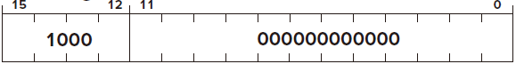
RTI
RTI stands for Return from Trap or Interrupt.
Opcode \(\text{[15:12]} = 1000\)
Operand
- \(\text{[11:0]}\) : must be
0000 0000 0000
FUNCTION
Condition Codes
TRAP Examples
Handling I/O
GETC or TRAP x20
TRAP_GETC   LDI     R0, KBSR
            BRzp    TRAP_GETC
            LDI     R0, KBDR
            RTI

KBSR        .FILL   xFE00
KBDR        .FILL   xFE02
OUT or TRAP x21
            ADD     R6, R6, #-1
            STR     R1, R6, #0

TRAP_OUT    LDI     R1, DSR
            BRzp    TRAP_OUT
            STI     R0, DDR

            LDR     R1, R6, #0
            ADD     R6, R6, #1
            RTI

DSR         .FILL   xFE04
DDR         .FILL   xFE06
PUTS or TRAP x22
            ADD     R6, R6, #-1
            STR     R0, R6, #0
            ADD     R6, R6, #-1
            STR     R1, R6, #0

            ADD     R1, R0, #0
TRAP_PUTS_LOOP
            LDR     R0, R1, #0
            BRz     TRAP_PUTS_DONE
            OUT
            ADD     R1, R1, #1
            BRnzp   TRAP_PUTS_LOOP

TRAP_PUTS_DONE
            LDR     R1, R6, #0
            ADD     R6, R6, #1
            LDR     R0, R6, #0
            ADD     R6, R6, #1
            RTI
IN or TRAP x23
            LEA     R0, TRAP_IN_MSG
            PUTS
            GETC
            OUT

            ADD     R6, R6, #-1
            STR     R0, R6, #0

            AND     R0, R0, #0
            ADD     R0, R0, x000A
            OUT                         ; Print LF

            LDR     R0, R6, #0
            ADD     R6, R6, #1
            RTI
TRAP_IN_MSG .STRINGZ    "\nInput a character> "
Halting the Computer
Recall the RUN latch is ANDed with the crystal oscillator.
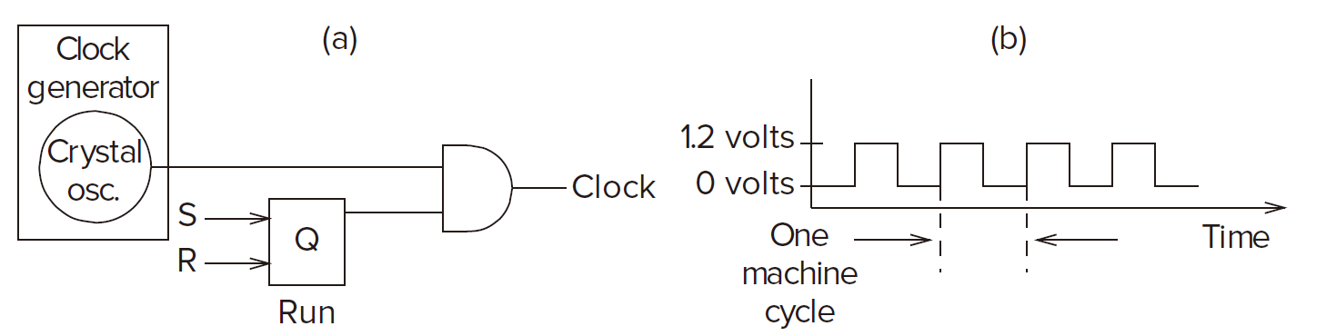
In the LC-3, the RUN latch is bit[15] of the Master Control Register (MCR), which is memory-mapped to the location \(\text{xFFFE}\). If bit[15] of MCR is cleared, then the computer halts.
HALT or TRAP x25
TRAP_HALT   LEA     R0, TRAP_HALT_MSG
            PUTS
            LDI     R0, MCR
            LD      R1, TRAP_HALT_MASK
            AND     R0, R0, R1
            STI     R0, MCR
            BRnzp   TRAP_HALT
MCR             .FILL   xFEEE
TRAP_HALT_MASK  .FILL   x7FFF
Interrupts and Interrupt-Driven I/O
What is Interrupt-Driven I/O ?
An I/O device that has nothing to do with the running program can
- force the running program to stop.
- have the processor execute a program that carries out the needs of the I/O device.
- have the stopped promgram resume execution as if nothing had happened.
Interrupt-Driven I/O Mechanism
Precondition to trigger an interrupt signal (INT)
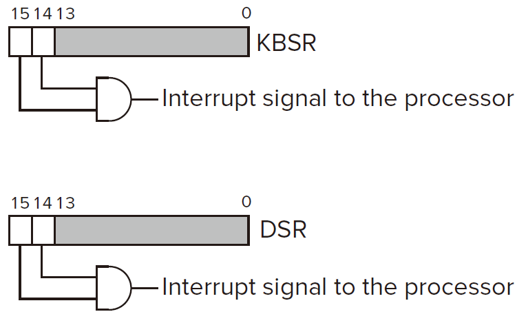
The device MUST WANT service
The I/O device wants service when the corresponding ready bit is set.
The device MUST HAVE THE RIGHT to request the service
In most I/O devices, the interrupt enable (IE) bit is part of the device status register.
In KBSR and DSR, the IE bit is bit[14].
The interrupt request signal from I/O device is the logical AND of IE bit and the ready bit.
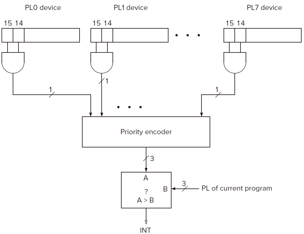
The deivce request MUST BE MORE URGENT than what the processor is currently doing
To successfully interrupt the running program, the priority of the request must be higher than the priority of the program wished to interrupt.
Test for INT
The INT Signal
To interrupt, the INT signal must be asserted.
The PL of each device are stored in the corresponding hardware.
Interrruption can happen at any time. But it makes much more sense to ignore interrupt signals except when we are at an instruction boundary.
At the first clock cycle of FETCH phase, it will test the INT signal to see whether it's asserted. If INT signal is asserted, then the next state is handling the interrupt request.
Handling the Interrrupt Request
Initiate the Interrupt
Save the State of the Interrupted Program
Push PC and PSR to the supervisor stack.
Load the State of the Interrupt Service Routine.
- Load PC
the mechanism of vectored interrupts.
If the interrupt is taken, the processor expands the 8-bit interrupt vector (INTV) to form a 16-bit address, which is an entry into the Interrupt Vector Table.
The Interrupt Vector Table consists of memory locations x0100 to x01FF, each containing the starting address of an interrupt service routine.
PC is loaded with the contents of location in the Interrupt Vector Table corresponding to the address formed by expanding INTV.
- Load PSR
PSR[2:0] contains no meaningful information. We arbitarily load it initailly with 010.
PSR[15] is set to 0.
PSR[10:8] is set to the priority level associated with the interrupt request.
Service the Interrupt
Return from the Interrupt, RTI
- Pop PSR and PC to the supervisor stack.
- Check whether change modes and the stack pointer.
创建日期: 2024.02.21 00:56:50 CST