Chapter 5 | The LC-3
ISA
The ISA specifies all the information about the computer that the software has to be aware of.
The ISA specifies the memory organization, register set, and instrction set, including the opcodes, data types, and addressing modes of the instructions in the instruction set.
Memory Organization
For LC-3, its address space is 216, its addressabilily is 16-bits.
We say LC-3 is word-addressable.
Similarly, if we say something is byte-addressable, then its addressabilily is 8-bits.
Registers
General Purpose Register (GPR)
The number of bits stored in each register is usually one word.
Register must be uniquely identifiable.
For LC-3, there are EIGHT GPRs.
Condition Code Register (CC)
LC-3 has three 1-bit registers which are individually set or cleared each time one of the 8 GPRs is stored as a result of execution of one of the operate instruction or one of the load instructions.
They are called N, Z, and P.
The Instruction Set
It's defined by its set of opcodes, data types and addressing modes.
Opcodes
15 instructions, each identified by its unique opcode which is specifided in bits [15:12] of the instruction.
Data Types
Every opcode will interpret the bit patterns of its operands according to the data type it is designed to support.
Addressing modes
A mechanism for specifying where the operand is located.
An operand can generally be found in memory or register or as a part of the instruction.
If the operand is a part of the instruction, we refer to it as a literal or as an immediate operand.
LC-3 supports FIVE addressing modes: immediate (or literal), register, and 3 memory addressing modes : PC-relative, indirect and Base+offset.
Operate Instructions
ADD
AND
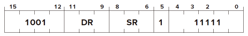
NOT
Opcode \(\text{[15:12]} = 1001\)
Operand
- \(\text{[11:9]}\) : DR
- \(\text{[8:6]}\) : SR
- \(\text{[5:0]}\) : must be
1 11111
FUNCTION
Condition Codes  : based on whether the result is negative, zero, or positive.
Data Movement Instructions
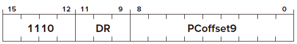
LEA
LEA stands for Load Effective Address.
Opcode \(\text{[15:12]} = 1110\)
Operand
- \(\text{[11:9]}\) : DR
- \(\text{[8:0]}\) : PCoffset (PC-Relative Mode)
FUNCTION
Condition Codes 
LD
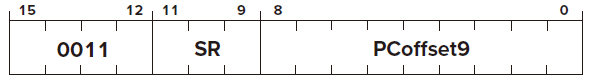
ST
Opcode \(\text{[15:12]} = 0011\)
Operand
- \(\text{[11:9]}\) : SR
- \(\text{[8:0]}\) : PCoffset (PC-Relative Mode)
FUNCTION
Condition Codes
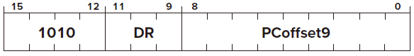
LDI
Opcode \(\text{[15:12]} = 1010\)
Operand
- \(\text{[11:9]}\) : DR
- \(\text{[8:0]}\) : PCoffset (Indirect Mode)
FUNCTION
Condition Codes : based on whether the value loaded is negative, zero, or positive.
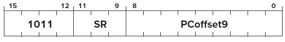
STI
Opcode \(\text{[15:12]} = 1011\)
Operand
- \(\text{[11:9]}\) : SR
- \(\text{[8:0]}\) : PCoffset (Indirect Mode)
FUNCTION
Condition Codes
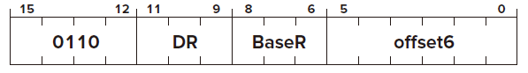
LDR
Opcode \(\text{[15:12]} = 0110\)
Operand
- \(\text{[11:9]}\) : DR
- \(\text{[8:6]}\) : BaseR
- \(\text{[5:0]}\) : offset (Base+offset Mode)
FUNCTION
Condition Codes : based on whether the value loaded is negative, zero, or positive.
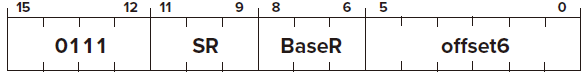
STR
Opcode \(\text{[15:12]} = 0111\)
Operand
- \(\text{[11:9]}\) : SR
- \(\text{[8:6]}\) : BaseR
- \(\text{[5:0]}\) : offset (Base+offset Mode)
FUNCTION
Condition Codes
Control Instructions
BR
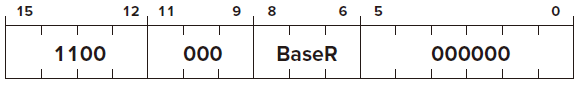
JMP
Opcode \(\text{[15:12]} = 1100\)
Operand
- \(\text{[11:9]}\) : SR
- \(\text{[8:6]}\) : BaseR
- \(\text{[5:0]}\) :
000000
FUNCTION
Condition Codes
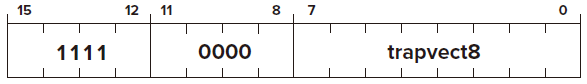
TRAP
or say service call.
Opcode \(\text{[15:12]} = 1111\) Operand
- \(\text{[11:8]}\) :
0000 - \(\text{[8:0]}\) : trapvector
FUNCTION
Condition Codes
The Data Path of the LC-3
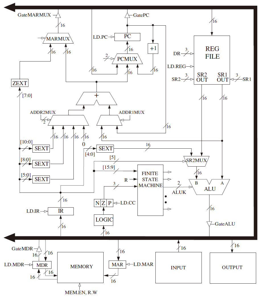
Basic Components
The Global Bus
It consists of 16 wires and associated eletronics.
Tristate Device
Each structure which supplies values to the bus has a triangle called a tristate device behind its input arrow to the bus.
Function
To enable exactly one supplier to provide infomation to the bus at any one time. LD.x (load enable) signal If it's asserted, the corresponding structure will obtain the value supplied.
Memory
To perform a load MAR -> Memory -> MDR
To perform a store MAR, MDR -> Memory with WE signal
The ALU and the Register File
Inputs of ALU
- Source 1 from a register
- Source 2 from either a register or the sign-extended immediate value
Outputs of ALU
- A result stored in one of the registers
- The THREE single-bit condition codes
The PC and the PCMUX
PCMUX selects the changed input of PC
- Incremented PC
- PC + PCoffset
- From the global bus (stack of memory)
The MARMUX
It selects which of two sources will supply the MAR with appropriate addressing during the execution of a load, a store, or a TRAP instruction. - Incremented PC / A base register / literal value - zero-extened trapvector, which is needed to invoke service calls
The Instruction Cycle Specific to the LC-3
创建日期: 2024.02.21 00:56:50 CST